
Suspended access
Ballasted outrigger beams
Two roof-mounted outrigger beams position the suspension ropes beyond the roof edge. Each beam uses front and rear support frames, inboard ballast and a rear tieback to a separate structural anchorage.
Explore this system in 3D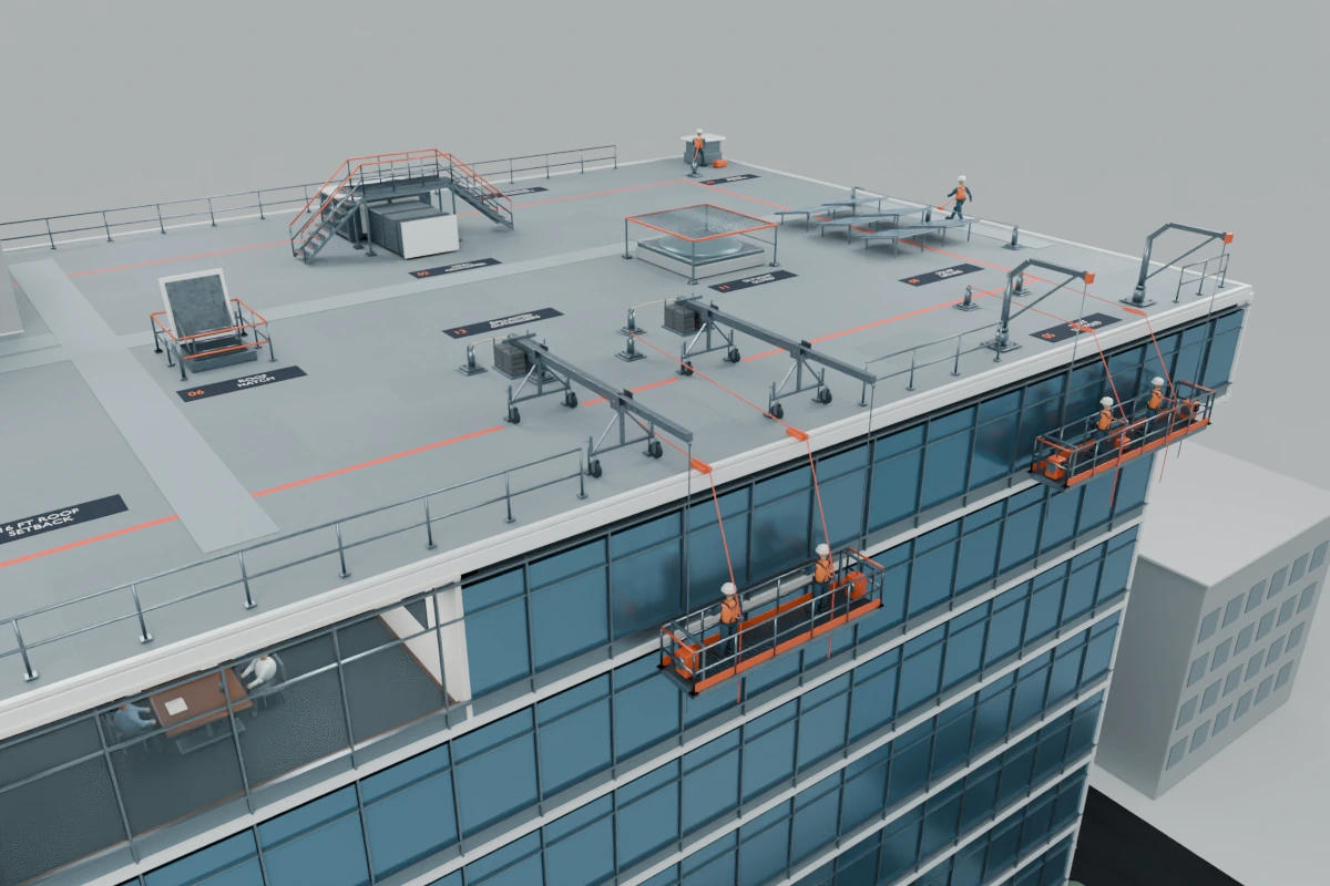
UNDERSTAND THE SYSTEM
Support the stage from paired roof outriggers.
- 01
Paired beams support the two ends of the suspended stage.
- 02
Each beam has wheeled support frames, inboard counterweights and its own tieback anchor.
- 03
Each of the two workers has a separate safety line attached to a separate roof anchor.
- 04
The model shows four distinct anchors: two for outrigger tiebacks and two for worker safety lines.
FROM REFERENCE TO ROOFTOP
Follow each connection.
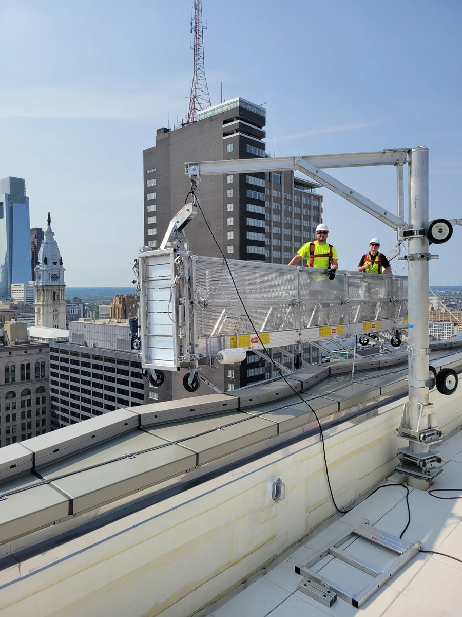
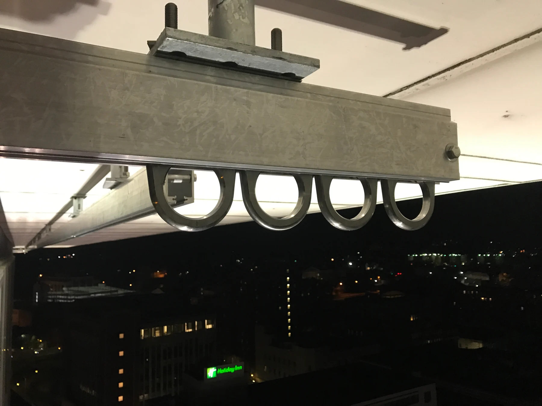
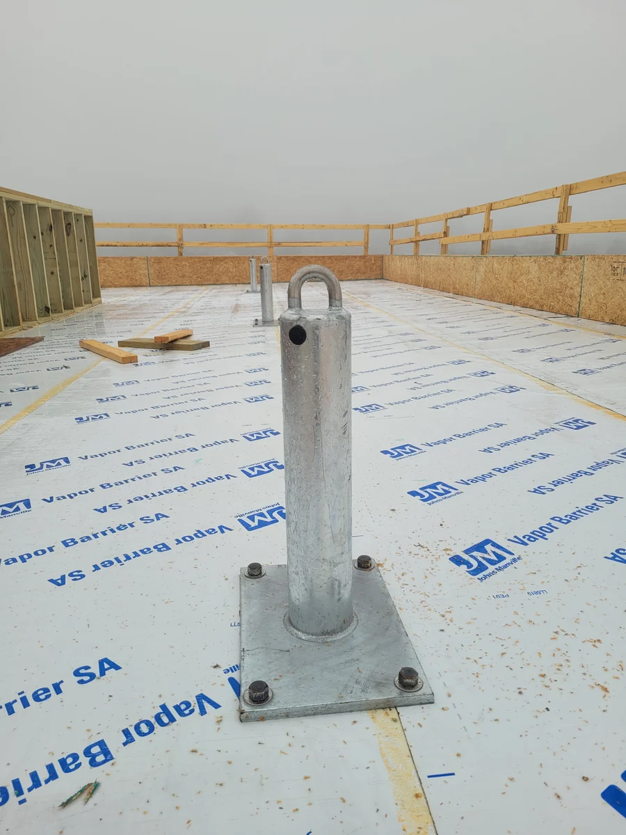
Explore the 3D model alongside the supplied outrigger reference illustrations.
KEEP EXPLORING
The next connection.
YOUR BUILDING. YOUR NEXT STEP.
Let’s talk about the work ahead.
Share your access needs with the American Anchor team.